Tuesday, February 24, 2015

Weekend Woodwork


One of the things I did for 452 project over the weekend was that I made a wooden speaker baffle.  As shown in the photo, I first drew circles that will fit the speaker.  The outer circle is drawn according to the size of the PVC speaker enclosure which is seen in the second photo.  After drawing the circles, I then used jigsaw to cut according to the line.  Using Gorilla Glue, I attached the pipe to the enclosure.  The final product is seen on the last three photos.  


Making this enclosure will make it possible to have variation on pipe length for different sound.  It is very simple to quickly install and uninstall the main pipe.  


Saturday, February 21, 2015

GameTrak right angle male headers mod

I got lucky while replacing the wires - I was able to force pairs of right angle male header pins into the spots where the wires used to be. These connections are now SOLID - I definitely suggest doing this if you like not being screwed by flimsy, glued wire.


My trial method:

Cut wire and scrape off glue using an x-acto knife. Leave only the soldered connections.
At a soldering station, heat up the solder and try to remove the wire end with the solder tip.***
Try to uncover the wire hole in the board. It doesn't need to be big.
Use the tip of the x-acto knife to scrape a larger hole in the solder.

Find a pair of right angle male header pins and gently force them through. (definitely not a perfect fit)
Apply solder at the connection.
Gently re-straighten the pins.
Insert pins into a breadboard and test!


*** You could be smart and not cut the wire before this step to make your life easier. Just heat up the solder and then pull the wire out of its socket.

Step forward, step back

Step forward:

The Scroll Accordion is well on its way. A file for the lasercutter is pretty much ready to go (thanks Isaac!) and the "backbone" arrived in the mail today. I put some of it together just a moment ago and it's looking pretty good!


The "backbone" is a 1/4" threaded steel rod (super cheap!) that conveniently fits through pre-existing holes in the GameTrak string receptacles. The rod I'm using is 1 foot long and the GameTraks are spaced 2 inches apart (at points 3", 5", 7", and 9") and are held there by 1/4" nuts. This will fit into my lasercut design, which I will update you with next week (I hope!).

Step back:

Flimsy, glued over 15+ year old solder connections are need to be treated with care. I've been carrying them around with me in my backpack without much protection and I'm now paying for that poor decision...


In case it's not clear, all those wires should be connected to those boards. The wires broke from the glue holding the soldered end in.

While this throws a wrench in my production schedule, it provides me an opportunity to strengthen the sensor connections. I will use a test GameTrak to experiment with removing glue and the original solder with hopes to replace them with right angle headers (or something else less prone to breaking in half). Should I be successful this would cut down on unnecessary wire length and also increase the durability of the instrument.

To-do list:
  1. Research a way to salvage the broken connections
  2. Wire up perfboard to accommodate multiplexor and all sensors
  3. Lasercut the enclosure
  4. Assemble the instrument
  5. Figure out how the heck I'm going to use all this data to make an engaging musical performance


Wednesday, February 18, 2015

Quick metal update!

So I ended up sourcing scrap-ish metal from Arlo (located on S. Industrial near the Re-Use center and such). This is a great place to find pretty nicely sized pieces for very little money - the picture you see below shows about 30 dollars worth of metal.

See ruler for scale - convenient accident.

For my project, I need all of this metal to move in response to magnetism. So following the EMvibe convention, I've glued small neodymium magnets using supposedly all-material Gorilla Glue. We'll see if this will hold up! I'll do another post when the whole system is plugged in together. 


I attached as many as I had reasonably sized clamps.
Finally, here is a picture of my first implementation of the LM1876 audio amplifier IC. With the help of Professor Gurevich, this has changed significantly and will be functional very soon!


Monday, February 16, 2015

Bernard Parmegiani, Étude Élastique

Bernard Parmegiani, Étude Élastique
The piece I mentioned in relation to Kevin's project last week.


Sunday, February 15, 2015

Speaker and Amp

I wanted make a quick blog about the speaker and amplifier that I'm using for this project since some people were curious.  

The amplifier that I'm using for this project is about $25, which is a very reasonable price.  The photo doesn't do it justice, but the blue lighting around the knob and the chrome plating are beautiful.  Most importantly, it sounds pretty nice.  It didn't cause much distortion when cranked up.

The speaker is only $10, and it can handle some pretty low frequency (low enough to resonate the PVC pipe around 180Hz), and it can produce some high frequencies too.  I played some commercial recordings, and they sounded surprisingly good for a $10 speaker.

(if anyone is curious about how they sound, feel free to ask me and try them out)

Amazon: Amp & speaker


Friday, February 13, 2015

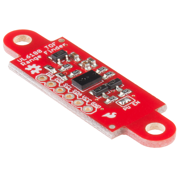
SparkFun ToF Range Finder Sensor - VL6180

New high-precision range finder with a breakout board that matches the Sharp IR rangefinder package: http://sfe.io/p12785

I2C interface, with voltage regulator onboard. Not super cheap though, at $25

Wednesday, February 11, 2015

Squishy Proof of Concept


This is a proof of working circuitry inside the mannequin that I will hopefully have soon. The conductive dough will be beneath a solid yet puncture-able material that is skin-colored. Conductive objects will include pins, nails, screws, etc. I want to hopefully include power tools.

Pendulum Prototype Process

For my project, I am attempting to build an instrument around the mechanic of Steve Reich's Pendulum music, a microphone swinging over a speaker. In extending this idea, I've decided to create multiple pendulums which activate different tambral effects when passing one another, In order to create polyrhythms between different swinging pendulums.

To begin this process I tested sensors that could be used to sense a pendulum passing and what pairs of speakers/microphones generated desirable/consistent feedback. The results were documented as follows:
SENSORS:
-Acrylic square swinging past distance sensor

-snappy response at distances 4.5-22.75 inches
-LEDs (ultrabright green) going past photocell
-noisy response in light at distances 0-3 inches
-noisy response in dark at distances 0-5 inches
-Neodymium magnet going past hall effects sensors
-noisy data within 1 inch of sensor

FEEDBACK SYSTEMS:
-Capacitive mic through arduino in front of 8 ohm speaker
-low low low fidelity, works more like switch than mic
-sounds horrible
-Boyscout earpiece as microphone swinging past 8 ohm speaker with laptop preamp
-nuanced feedback within 4.5” of speaker
-sounds cool when frequency shifted in MAX

I concluded that the IR distance sensor was the ideal sensing mechanism for this project and that the boyscout earpiece reversed to be a microphone over the little 8 ohm speaker would be most reliable and desirable for the project.

Then I designed a structure that I could swing things from and sense their passing. The sketch looked like this:

I designed all of the parts for laser cutting a 2 pendulum (thinner) version of this structure, I printed it out and it turned out like this:
It works! The microphone on the left pendulum swings over the speaker and its passage of the other pendulum triggers a modulation of the feedback frequency, meaning that as the left block passes the origin it creates a rhythm and as it passes the other block it creates a polyrhythm. Solid!

It is already pretty fun to play but offers mainly 3 modalities:
-full on feedback from right pendulum and moving left to play the modulation rhythmically
-free swinging right phasing with freeswinging left creating a polyrhythm with a variable duty cycle
-tapping on the right cube to make drum-style rhythms while moving the left to modulate

I'm excited to add more pendulums to increase the possibility for more complex interactions to work with. 

Many design flaws (note pipe cleaner and hacked support stand) are due to mis-measuring. 
Making this prototype out of plywood found in someones yard and in the Design Lab scrap pile has helped me evaluate the way I'm supporting structure and making me realize (with some help from Professor Gurevich) that I could benefit from a second shaft connecting the stands in addition to a stand somewhere in the middle that'll support it between the pendulums. I also need a proper amplifier for my little 8 ohm speaker and a place to mount all the components.

I will post a video demo soon, the one I already recorded has piercing audio because of my cell phone microphone trying to interpret feedback noise as a human voice... pretty piercing.


Monday, February 9, 2015

Making Squishy Circuits!

After following the instructions that were linked in a previous post (http://makezine.com/projects/squishy-circuits/) I had a couple pounds of conductive dough in an easy twenty minutes.

1.2.

3.4.


A test LED with batteries in serial was able to light up and stay lit without wavering. It felt very breadboard-esque sticking the connectors in the dough! Dough-board?


My next test was to stick the conductive things through fabric. I figure it would work for obvious reasons, but I just wanted to make sure my primary mode of interaction would work...


...And it did!

Last, since in my excitement I didn't make insulating dough for it, I wanted to see how much loss there was through a long run of Squish.

Here's the track...

This is the voltage at the beginning...

This is the voltage after the track.

Around 3% loss is nice, but the insulating dough may still be necessary because my design will likely be having different doughs close to each other.

So the point is that the dough, albeit un-insulated, is able to reliably conduct, and its squishiness will compliment me sticking things through it without breaking, shattering, scratching, etc. With other hardware and good coding, I'm on my way to a performance system!

Wednesday, February 4, 2015

Guide to GameTrak (dis/re)assembly

This is a quick guide to disassembling parts from a GameTrak and reassembling them into a more useful configuration.

To open the GameTrak you first need to rip off the feet cushions on the bottom of the controller. The screws are hidden under them.


Once you've done that you can pull the top cover off and start taking out the weights (in the corners). It will look somewhat like the picture below (I've taken out one of the string mechanisms already).


Start unscrewing the string receptacle (the big container with the wires going into it). BE CAREFUL: be sure to only unscrew the parts connecting the receptacle to the base (the corners, in slightly deeper holes), not the screws that keep the container together.

If you take apart the container you will have a really greasy constant force spring unravelling into your face. It is not pleasant. Another reason to not take it apart is because the potentiometer contraption that reads the string length only works when the spring is in place. Without it, you can only read X and Y position from the joystick.

I'm guessing most people aren't going to want the wheel below the joystick. Removing the wheel requires clipping the washer on the left side of the spoke (in the picture below) with a small wire cutter and then you can just push the spoke out from the wheel.

Alternatively, you can unscrew the wheel holder from the base. You'll have to unscrew the joystick board from the top in order to access the screw underneath it (also shown in the picture below).


You can cut the wires at any time - just make sure you'll have enough length from each component to solder extensions. 

At this point you should have the string receptacle and the joystick board free from the base.

Fortunately for us, the GameTrak manufacturers originally designed the joystick board to fit on the end of the string receptacle. Evidence of this is the weird looking end on the string receptacle (bottom left photo), which fits the joystick perfectly. The board snaps in easily, perfectly lined up with the opening in the string receptacle (bottom right pic).


And there you have it! It has all the functionality of a GameTrak in a compact, portable configuration. Plug the wires into an Arduino and you have a pretty slick X, Y, and string length sensor.


Sunday, February 1, 2015

Squishy Circuits

Alex and I were talking last week about the possibility of turning a mannequin or mannequin-like object into a big circuit, and maybe translating the idea of massaging it to applying "acupuncture" (sticking needles, nails, etc., into it to create circuits.

Check out this Make article on Squishy Circuits: http://makezine.com/projects/squishy-circuits/