Thursday, April 30, 2015

Making a shape out of wood.

So, I regrettably don't have a lot of photos still of the first project we did this year, but I do have a couple of photos from the process of making my octagon, so I figured I would make a quick write up. 

The first step was cutting all the boards to the length of an outside edge! Then, beveled edges at 1/2 the angle of the shape you're making. I also cut this wedge of the bottom to make space for tuners. All of this is done on a table saw and is relatively straightforward if you go slow and have a miter gauge!

When working with plywood, you're usually good to glue with no fancy joinery up to a miter of 45 degrees. However, solid wood requires either a finger joint (easy for a square) or a tongue and groove joint in the case of the octagon. This is to keep our ratio of end grain to long grain in check. Long grain is good for glue joints and end grain is useless!


With all the sides cut, I put them end to end and used packing tape to go over every joint.


Which allows flipping the whole system over! Then it's time to apply the glue.


After glue is on every edge, the tape is used to tension the boards into shape, but "closing" the loop. Then tape goes across, around, back and forth and everywhere.


That's pretty much it!


Installation Project documentation!


Here is a blog post detailing the process of making this installation:

The original concept here was to build an environment for meditation, and I was enamored with the idea of a box for quite some time. I spent a lot of hours in my basement prototyping joints that I didn't end up using, but it was definitely a valuable experience in terms of refining a process! This is a glue up I did of the joinery that I will use eventually to make the box:


After some friendly prodding from Eric, Takumi, Kevin, co. I was convinced that a box is NOT an interactive art installation, and that I should build the interactive, functional part of it first. So, I worked with my test rig from last project (the old trusty guitar amp) and found a few sheets of metal that I really liked the sound of, and that I could glue a magnet to in a place of actuation. From there, building a reliable and simple mounting solution was the next step. I tried a few ideas, but the sturdiest and best sounding was simply a 2x4 with the end recessed for the magnet. Here's a prototype in action:

One of the stupid little bugs of this project was not having the right size of screws! But I fixed this with a whole saw. It also keeps the screw out of the way for when I finally but these in a larger structure.


The next (daunting) step was finally conquering the amplifier question. One of the problems I had with the last project was dealing with the complicated "mute" and "standby" pins on the LM1876. It also had a pretty fussy power supply window of operation. For this project, I opted for the simpler, one channel LM1875. I was able to assemble the circuit below, which is basically just running the signal through the amplifier with a few filters. I also have capacitors used to bias the power supply into true -12v, 0v, 12v submission. This is done with a large and small cap (1000uF and 0.1uF) in between -V/+V and GND,  respectively. 


Once this was done, I made nicer versions of the mounts and reduced the noise with some rubber stoppers. The final systems came out really nicely, with the perfect alignment between magnets and a good amount of structural integrity. Also, some sanding and nice stain. Polycrilic is to come!


Not pictured here is the journey of creation I took with the meditation object (aka pokey pyramid). This was a super important part of the interaction so I dedicated a lot of time and thought into how it should feel and look. I ended up cutting a design on the band saw out of sheet metal, bending it into shape, and texturing it with weld material. Then I sandblasted it, used gun blue to get a darker finish and waxed it to seal the metal from oxidization.


Tuesday, April 28, 2015

Wireless Arduino-To-Arduino Communication

For my project, one of the arduinos needed to freely rotate, so I couldn't just run a wire from one to the other. So, I started looking at different wireless modules and found this post on stackexchange really helpful in explaining the differences between all of them. In my case, I could have gone with the XBee, the Nordic nRF24L01, or a barebones radio transmitter and a receiver. The latter might have been too unreliable due to interference, and the XBee was a bit expensive (also I had heard they were hard to configure.) So, I ended up going with this nRF24L01 breakout from Sparkfun, and I'm really glad I did. (You can even get them way cheaper on amazon if you're fine with an on-chip antenna).

The first step is connecting to your arduino. To figure out which pins to use, read the Connections section here. I used the muli-purpose IO pins (11, 12, & 13) for one arduino and the ICSP pins for the other; either works fine. Also, the library I used defaults to pins 7 and 8 for CSN and CE, respectively, but you can change these to whatever you want. I used 8 and 9.

Speaking of libraries, here it is. I like this one better than some of the alternatives because it seems like the interface is as simple as possible, while still using the nordic's auto-retransmit and auto-acknowledge features to ensure your packet always gets where it needs to go. The first link in the github readme gives some example code, which is more or less exactly what I used. To see specifically what I did, check out my code on github here.

Monday, April 27, 2015

Hiding the Menu Bar

Here is a quick post about something I found very useful for this project.

Since I'm displaying video feeds on my laptop screen, I needed a way to hide the menu bar.

The way to do that is very simple...
Just create two message objects as shown in the photo.  Then click on them to hide/unhide the menu bar.

UPDATE:  You can do the same with mouse cursors!

Sunday, April 26, 2015

Jitter Journey - Detecting Movement


My project mainly consists of Jitter, so I'm going to make some blog posts about what I did with it.

For the interaction, I wanted Max to detect motion and use the motion data to manipulate sound and visual.  Luckily, somebody made a patcher that fulfilled my need.

Hold Still is a patcher that uses frame-differencing to detect movement.  This simple and straightforward patcher uses video sensing to control sound synthesis.  

Hold Still is #32 in the Jitter Recipes. Download the patch here
You can read more specific details about how it works on that link.

I mapped the movement values to groove~ object to manipulate a glitch audio file.  The amplitude of the outputted sound is then mapped to jit.sprinkle object to manipulate the video feed.  

I also used Hold Still patcher to sense if a person is looking into the peephole or not.  I set the threshold very low in order to detect slight eye movement.

It looks like Isaac is using Hold Still for his project as well!

Very useful.


Thursday, April 23, 2015

I apologize for the vertical camera footage, but progress has been made! Here I am having the program draw a red dot where I push-- calibration is still a little off, and I'm honestly not totally sure what I did to make this work (I had been trying so many things for the last 10 hours, and it just started working, with some combination of those things) woohoo!

Tuesday, April 21, 2015


This is more or less a proof of concept for the users' interface, as well as a demonstration of state change while users interact (or don't!) with her. Along with the two pushbuttons, the LCD object in Max will likely be the only interface that the users will have. I'm probably going to display LCD on a separate monitor next to the fish tank. This allows me to position my computer more conveniently to hook things up, and it frees up a lot of space for the buttons.

Monday, April 20, 2015


 Projection mapped in Processing and depth sensing, trying to combine the two now!

Rosella's Modern Life


These are some storyline sketches. This project will be story-based and "constructed." The things I will be lowering into Rosella's aquarium will be generic because I want the narrative to shape the interaction. The crux of the piece is that while all it really is is a fishtank with a snail inside, we're inclined to assign value and sentiment to Rosella and the things we drop into the tank.

Speaking of dropping things into a tank, I was able to use a continuous servo to drop an item in:


Since the screen will be the peoples' main interface, I want to do the project in Max. Maxuino fits my needs perfectly, since all the Arduino is doing in this project is lowering and raising objects. As shown in the video, all I need are some timed bangs on float boxes to get them spinning equivalent distances. That's also as fast as I could make the servos spin, but that's not a complaint. Don't want to crush Rosella.

Two buttons will be the primary mode of interaction, with each button deciding what Rosella "does" in her life. I want it to be similar to the King's Quest series, or maybe more true to the concept, Peasant's Quest by HomeStarRunner. The narrative will be completely ridiculous.
  • Rosella goes to the mall.
  • She (you) decides to fill out one of those "win a boat" sweepstakes forms you see all the time
  • She miraculously wins the sweepstakes two weeks later but the company fulfills the sweepstakes has since been foreclosed
  • As a "consolation prize," they give her the (now ex-) CEO's firstborn child, Frank
    • A generic snail toy model is lowered into the tank
  • Rosella goes about her business, encountering other events
  • 5 real minutes later, Frank runs away, leaving a note that says he left to "find his passion in above-water basket weaving"
    • The snail model is raised back up
Moving forward I would like to create a structure out of wood that holds servos securely and is able to securely sit on the top of the fishtank. I see laser cutting in my immediate future.

Sunday, April 19, 2015

This post is half project update, half rant about the Xbox Kinect/Windows Kinect, and the incredible struggle it has been to get the Kinect to "connect" buh dum chee!

It's now been about two weeks of wrestling with these products to talk to my computer. Basically, I tried EVERYTHING! I struggled to get them working on Mac, but had huge problems with out of date software and drivers. A basic summary: Two versions of Open NI: Simple Open NI and Open NI 2.0. After Open NI 2.0 was made the project was shut down, and this was several years ago. Since many new products have come out since, a lot of the tutorials have unanswered recent questions on how to get these new hardware devices to work with old software and old sample code. Also, almost everything you will find online about this is an unorganized mess!! It's scattered around by users instead of put out by the developers. Windows makes the Kinect and Windows or Mac do not really seem to want to make it work easily on a Mac. Fine, I get that. So I downloaded the Bootcamp Windows 8 Partition on my computer. That resulted in a whole slew of other problems, with drivers not working at first, internet not connecting as a result, blah blah blah, got that worked out eventually.

Got everything going and didn't have enough space to install the software. Moral of the story I learned- DO NOT give Bootcamp the minimum amount of space required for installation, cause then it's useless if you want to do anything on it. Reinstalled Bootcamp with more space. Okay! Should work now! NOPE.

I already hated Microsoft a bit, since memories of my insanely slow and old Dell computer at home are pretty much all I associate with the company. But the uninformative website, complete lack of helpful information in error messages, and totally incompetent help phone line has taken my burning hate for Microsoft to a whole new level. I digress, basically, if you have the newest version of the Kinect for Windows (2.0!! NOT IN THE TITLE! THEY DIDN'T NAME TWO VERSIONS DIFFERENTLY!) then, I would assume, if you download the software for the updated SDK 2.0 on the Kinect for Windows website, you will have it working perfect in no time. However, there is an older model of the Kinect for Windows, with a different model number, that is super easy to differentiate because it looks different, and yet there is no place to "click here if your Kinect for Windows looks like this and download the OLDER SDK drivers." Anyways, rant over, that was the solution. The older SDK drivers got the Kinect to connect! Still only running samples, have to figure out how to get the sample code into a compiler that I can pick up and run with for my project. Also still having issues getting Touch Designer working, I have the NIVIDIA graphics card you need, but it seems mine may be a different model. Overall, finally made some progress. Final thoughts: Mac needs to come out with an alternative to the Kinect or better integration! Windows is the worst, forever and always.

TL;DR
I hate Microsoft. Finally got the Kinect to be seen by the computer though.

Thursday, April 16, 2015

ESP Levitation (actually just a webcam and a fan)

For my project I decided to do an interactive alternative to Erwin Redl's "Ascension (thirty-one)"  using a pretty similar mechanism, a ball in a tube being levitated by a fan. The video above is me playing with the prototype, made with acrylic tubing, a squirrel cage fan (from sparkfun), plywood, a ping pong ball, a mosfet, an arduino and a webcam. Imagine its like the worlds fair or something, and stay tuned for the upscaled (not janky) version!

Sunday, March 15, 2015

Explaining the witchcraft behind the Time Organ

I had originally planned on writing about the physical process of creating my Time Organ, but looking now at how things turned out, I think discussing the software behind it will be more interesting. (As far as the physical device, I'd say the most important takeaway is that these Rock Band Keyboards are fantastically cheap, have 25 keys w/ velocity, a touch sensor strip, a MIDI out port, and a ton of room inside for sensors and wires and junk, so you should all buy one to mess around with.)

First off: the code is all here on github for anyone curious – I tried my best to keep things well organized, although the commenting can be sparse in places. The majority of the logic is in Max (plus some amounts of arduino and javascript code), with the functionality split up into several main patchers, embedded in bpatchers here in main.maxpat:


The core features to think about are:
  • A custom granular synth engine that 
    • can draw grains from live recordings as well as pre-recorded samples
    • reacts in real-time to parameter changes
    • uses a Hanning window to smooth in and out of grains
    • operates on the scale of milliseconds, rather than microseconds like many other gran-synth setups
  • The gran-synth output is then piped through a poly~ object and pitch-shifted based on MIDI key input, so the sound can be played polyphonically.
  • The pattrstorage object is used (even though it crashes Max every time) to save presets of buffer contents, grain windows, and other parameters, which can then be recalled by button presses from the arduino.
  • A stutter~ object is constantly recording the last 5 seconds of audio from channel 2, and when the "freeze" button is pressed, that buffer is copied to the gran-synth engine's buffer.
  • The patch actually doesn't require the physical device to mess around with – try flipping the toggle on near that lower keyboard, and fiddling with the keys and some other controls to see what happens.
I'll start by talking about the granular synth stuff. The patches in my actual project have gotten pretty complex for the sake of supporting things like stereo, bypassing certain effects, and loading default values, but the core concepts are pretty intuitive. Here are simplified versions of the patch "granvolution" and the patch "polygrain" inside of it, which is loaded inside the poly~ object:
So there are really just 3 main things going on: The polygrain~ patch plays the grain when it gets a bang, multiplies the output by the hanning window generated by the fadecurve patch I wrote (the details of which aren't very important – just think of it as a smoother adsr~), and then outside the poly~, the whole repeated stream of sounds gets multiplied by the average amplitude from my other mic to allow breath control of volume.

Then the "tailfx" patch you see at the end there handles the pitch shifting, compression, and reverb:

(The pitchshift, reverb, and compress patches are all other custom ones, but they do pretty much what you'd expect, so no need to dive into that.) 

The last main piece, but probably the one most relevant to other people in this class, is the patch inside controller.maxpat, called arduino-buttons.maxpat:
This uses Max's javascript support for parsing and sending serial data, which I think is a great choice for those who like to maintain their sanity, since Max doesn't technically even have the concept of a string type. I'll let anyone curious check out the scripts themselves on github, but the main idea is this: messages are sent using readable ASCII characters, instead of binary data (avoids the need for bitwise operations), and each message sent uses a single character at the beginning as an identifier (b for button, p for potentiometer, r for reverb, etc.) followed by some more characters encoding the data it wants to communicate. Something like "s 1 0" from the arduino to Max means that switch 1 was turned off. Or "r 65" from Max to arduino means that I set reverb to 65%, so it should print that to the LCD screen so the performer has that feedback.

parseSerial.js has a few functions named after these identifiers (b(), p(), s(), etc) which are automatically called when the object receives a message starting with that symbol. Then it cleans up the data and sends it out the outlets in a Max-friendly way. toSerial.js basically does the opposite, but in a much more general way – it will turn any list of characters into a list of bytes, perfect for sending to the serial object. Feel free to use these ideas or the code itself in your projects to make communicating over serial in Max a little easier!


Thursday, March 12, 2015

Powering LED

I wanted to use addressable LED strip for probably more than a year now and I finally got the chance to use it!  I was always afraid that it was complicating to use, but it was surprisingly not that difficult.

Here is a brief steps that I took to power the strip.  If you want to know more about the specific details, please feel free to ask me.

I bought the strips from Sparkfun (SPARKFUN LED STRIP) last semester for 451 project even though I didn't get the chance to actually incorporate it in the game.  The hookup guide that can be found in that link was VERY useful and straightforward.  Once I got power, it didn't take too long until I figured out how to control the lighting using sensors; programming on Arduino was pretty straightforward.

It was powering that confused me.  I completely underestimated how much current each strip eats up.
^So, I ended up using this power supply. JamecoPowerSupply

First thing I did as soon as I got it was to find an AC cable and then stripping it up to obtain three cables inside (as shown in the photo above).  Spade terminal is used to connect things.


^Double row terminal blocks were used (one for ground and the other for vcc)  

^Overall picture of how everything is setup


Can multiple addressable LED strips be controlled using only one Arduino code?  YES!
I just used two different PWM pins and made a second LED strip class within the code.  Controlling it with a sensor wasn't that bad either!

Can't wait to use it more in the future.


Friday, March 6, 2015

Connecting Things Together

Here is a blog post about how I'm connecting things together (and it worked!)

Because I will have each pipe and Arduino separate by few feet, I needed a way to have all the wirings minimal and clean.    


After consulting with Professor Gurevich, I decided to use an ethernet cable to connect the sensors and LED strips on each pipe to the Arduino.  
If I didn't use an ethernet cable, I would have total of 9 wires coming from each pipe.  Since I have 4 pipes total, there would be 36 wires!  Instead of 36 wires, I only have 4 ethernet cables total.  Clean is good...


^This is what's on bottom of every pipe.  Speaker terminal and ethernet cable terminal.


^I soldered the ethernet terminal and some male hdr pins onto a perf board.  All the wires from the sensors and LED are connected here.


                                                                  ^On Arduino's side


 All the sensor datas are sent to Arduino with no problem.  It was definitely worth it!


Thursday, March 5, 2015

Updated string accordion proof of concept


I should've had this done last week... ah well. It doesn't help that I was sick all spring break until just today! I'm just catching up now.

Just getting to this point took considerable effort even with everything built and coded. A few uncooperative connections made for several hours of work today.

A new instrument housing is more necessary than I thought. The parts simply need to fit together better for this to work properly and with any hope of durability. Enclosure 1.0.2 is on the docket for tomorrow (altered lasercut file and then a walk across the street to the woodshop).

Tuesday, February 24, 2015

Weekend Woodwork


One of the things I did for 452 project over the weekend was that I made a wooden speaker baffle.  As shown in the photo, I first drew circles that will fit the speaker.  The outer circle is drawn according to the size of the PVC speaker enclosure which is seen in the second photo.  After drawing the circles, I then used jigsaw to cut according to the line.  Using Gorilla Glue, I attached the pipe to the enclosure.  The final product is seen on the last three photos.  


Making this enclosure will make it possible to have variation on pipe length for different sound.  It is very simple to quickly install and uninstall the main pipe.  


Saturday, February 21, 2015

GameTrak right angle male headers mod

I got lucky while replacing the wires - I was able to force pairs of right angle male header pins into the spots where the wires used to be. These connections are now SOLID - I definitely suggest doing this if you like not being screwed by flimsy, glued wire.


My trial method:

Cut wire and scrape off glue using an x-acto knife. Leave only the soldered connections.
At a soldering station, heat up the solder and try to remove the wire end with the solder tip.***
Try to uncover the wire hole in the board. It doesn't need to be big.
Use the tip of the x-acto knife to scrape a larger hole in the solder.

Find a pair of right angle male header pins and gently force them through. (definitely not a perfect fit)
Apply solder at the connection.
Gently re-straighten the pins.
Insert pins into a breadboard and test!


*** You could be smart and not cut the wire before this step to make your life easier. Just heat up the solder and then pull the wire out of its socket.

Step forward, step back

Step forward:

The Scroll Accordion is well on its way. A file for the lasercutter is pretty much ready to go (thanks Isaac!) and the "backbone" arrived in the mail today. I put some of it together just a moment ago and it's looking pretty good!


The "backbone" is a 1/4" threaded steel rod (super cheap!) that conveniently fits through pre-existing holes in the GameTrak string receptacles. The rod I'm using is 1 foot long and the GameTraks are spaced 2 inches apart (at points 3", 5", 7", and 9") and are held there by 1/4" nuts. This will fit into my lasercut design, which I will update you with next week (I hope!).

Step back:

Flimsy, glued over 15+ year old solder connections are need to be treated with care. I've been carrying them around with me in my backpack without much protection and I'm now paying for that poor decision...


In case it's not clear, all those wires should be connected to those boards. The wires broke from the glue holding the soldered end in.

While this throws a wrench in my production schedule, it provides me an opportunity to strengthen the sensor connections. I will use a test GameTrak to experiment with removing glue and the original solder with hopes to replace them with right angle headers (or something else less prone to breaking in half). Should I be successful this would cut down on unnecessary wire length and also increase the durability of the instrument.

To-do list:
  1. Research a way to salvage the broken connections
  2. Wire up perfboard to accommodate multiplexor and all sensors
  3. Lasercut the enclosure
  4. Assemble the instrument
  5. Figure out how the heck I'm going to use all this data to make an engaging musical performance


Wednesday, February 18, 2015

Quick metal update!

So I ended up sourcing scrap-ish metal from Arlo (located on S. Industrial near the Re-Use center and such). This is a great place to find pretty nicely sized pieces for very little money - the picture you see below shows about 30 dollars worth of metal.

See ruler for scale - convenient accident.

For my project, I need all of this metal to move in response to magnetism. So following the EMvibe convention, I've glued small neodymium magnets using supposedly all-material Gorilla Glue. We'll see if this will hold up! I'll do another post when the whole system is plugged in together. 


I attached as many as I had reasonably sized clamps.
Finally, here is a picture of my first implementation of the LM1876 audio amplifier IC. With the help of Professor Gurevich, this has changed significantly and will be functional very soon!


Monday, February 16, 2015

Bernard Parmegiani, Étude Élastique

Bernard Parmegiani, Étude Élastique
The piece I mentioned in relation to Kevin's project last week.


Sunday, February 15, 2015

Speaker and Amp

I wanted make a quick blog about the speaker and amplifier that I'm using for this project since some people were curious.  

The amplifier that I'm using for this project is about $25, which is a very reasonable price.  The photo doesn't do it justice, but the blue lighting around the knob and the chrome plating are beautiful.  Most importantly, it sounds pretty nice.  It didn't cause much distortion when cranked up.

The speaker is only $10, and it can handle some pretty low frequency (low enough to resonate the PVC pipe around 180Hz), and it can produce some high frequencies too.  I played some commercial recordings, and they sounded surprisingly good for a $10 speaker.

(if anyone is curious about how they sound, feel free to ask me and try them out)

Amazon: Amp & speaker


Friday, February 13, 2015

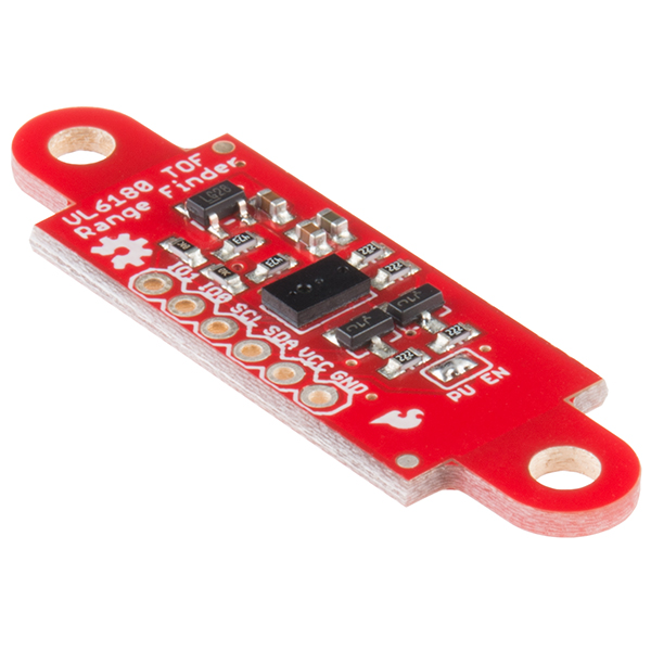
SparkFun ToF Range Finder Sensor - VL6180

New high-precision range finder with a breakout board that matches the Sharp IR rangefinder package: http://sfe.io/p12785

I2C interface, with voltage regulator onboard. Not super cheap though, at $25