
So first, the good things. It's great to have the object in my hand, to be able to play with it and feel it's strengths and weaknesses. The interaction feels much as I imagined it, and the scale to the human hand is just about right. The assembly was fairly straightforward and how I imagined it...no 'oops I didn't think of that.' Also, I was able to get it into the hands of my design focus group (my wife) for immediate evaluation and feedback. For a first iteration, I'm very satisfied. Emphasis on first iteration.
The bad things. Because of the nature of the 3d printing process (I still prefer the word Stereo-lithography, but for the sake of clarity I'll go the more prosaic route), both the housing and the plunger are covered with tiny, horizontal ribs. This makes the action in and out rough, though I imagine it will get better with time as use smooths out the inside. I could have also spent a few hours sanding it, but I decided that I wanted to get it assembled and out for a test drive before I committed to putting that time in. I used elastic cord for the compression elements, and I think I would rather use metal springs as the cord is just not strong enough to provide a satisfying resistance. I'm also a little concerned that the plunge depth is not deep enough to have a wide range of sensor data that will be needed for maximum expressiveness. The solution of course is to make the housing cylinder longer, but then the device starts to move out of the 'hand sized' scale that I was trying to adhere to. I also think the ring could be a little larger, so in the next iteration I'm going to have to strike a balance between those two opposing concerns. The results of the focus group testing proved inconclusive. When she first interacted with it she didn't roll it around on the ring like I envisioned. I thought the design just begged for that motion, but apparently it didn't. All is not lost, it may become more apparent when there is feedback (sound) hooked up to the interface and the movement is tied to that.
Moving over to the electronics department...

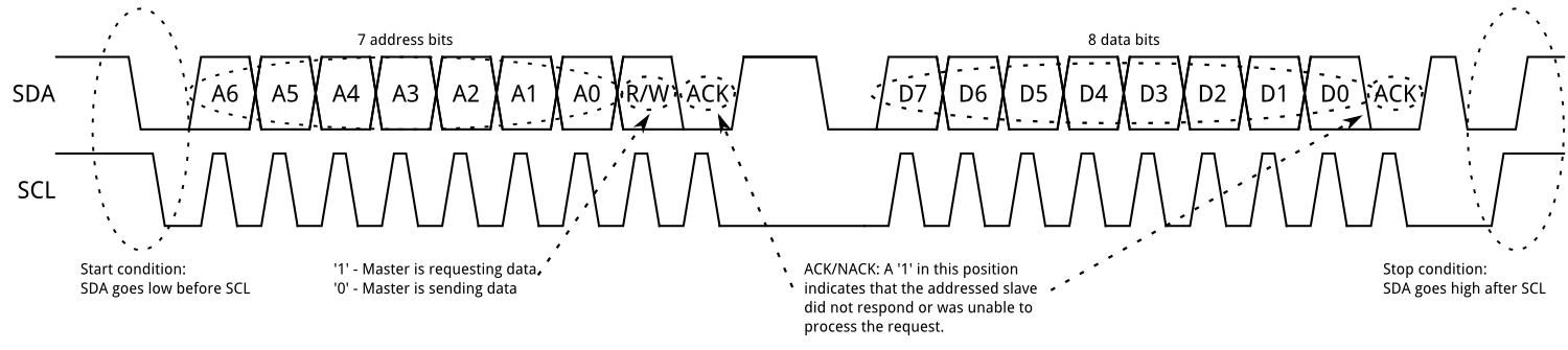
The i2c bus works like a charm! I've wanted to try out sensors using i2c for a while, and this was a perfect opportunity. The i2c bus is an old but proven technology that uses a data line and a clock line (SDA and SCL) to move information through your circuit. So instead of running a bunch of wires back to the microcontroller for each sensor reading, you only send these two wires. On each sensor, or slave, device there is a small addressing microcontroller, and the i2c protocol sorts all of it out for smooth sensor data from multiple devices over minimal material. The i2c works by varying the length of data pulses around the steady clock pulses. Found a informative graphic on Sparkfun:
Adafruit supplied the chips and as usual a super friendly library and scads of documentation. It turns out that they supply so many different sensors and upgrades to their old sensors that they have come up with a meta-library to handle reading the sensors for all of their products. It's called the Unified Sensor Library and it makes getting data as easy as calling a member function of a declared object.
Now that I've got the data, I've got to figure out what to do with it. XYZ orientation data is the obvious choice, and I don't really even need the X data, which would tell me which way the object is turned from magnetic north. I'll end up mapping the Y and Z data to the unit circle on a polar as opposed to cartesian graph, and then adjusting the scale of the graph based on the depth of the plunger in order to compensate for different readings for different elevations of the plunger. Or something like that, my math is a little rusty in this area so I'm just going on hunches at this point. But it looks good on paper!
No comments :
Post a Comment
Note: Only a member of this blog may post a comment.